PUMP SYSTEM FORMULAS (METRIC UNITS)
This page contains many applets to help you do calculations and to SAVE YOU TIME.
Many of these applets have been replaced with more conventional web apps
(problem viewing applets)
Flow vs. velocity
Normally, the flow rate is given, it is fixed by the user or the requirements of the process. For a new system the pipe diameter is unknown, with the flow rate and a trial estimate of the pipe size it is possible to see if the velocity will be in the desirable range as given at this page.
Pressure vs. pressure head or fluid column height
Head is one of the main characterisitics of a pump. In the imperial system it is measured in feet. If the maximum discharge head of a pump is say 10 meter, the fluid will be able to get to 10 m of height above the discharge and the flow will be zero. The head of the pump depends on the flow rate and it is zero at the maximum head and diminishes as the flow increases. To verify the discharge head of a pump, a pressure gauge is used. Pressure gauges measure in units called psi or pounds per square inch. The formula gives the conversion of pressure to head.
more infoand to do your own head and pressure calculations with this java applet![]()
Total Head
see Figure A-1 at bottom for location and meaning of subscripts (more info
Pump shaft brake power
Power is given by the combination of four items: the specific gravity SG, the total head ![]() ,
the flow rate Q and the efficiency of the pump eta
,
the flow rate Q and the efficiency of the pump eta ![]() . The specific gravity SG is the ratio of the
fluid's density to that of water at standard conditions, for water the value of SG equals 1.
The total head is normally calculated for the flow rate of the system and depends on static head,
pipe friction loss and equipment loss, it can also be measured with pressure gauges. Two pressure gauges
are required, one on the discharge and one on the suction side of the pump. The difference between these
two measurements is taken and the 2nd formula above is used to convert to head. And finally, the
efficiency of the pump must be known, this is usually obtained from the pump manufacturer's
total heads vs. flow curve of the pump (see typical pump curve).
. The specific gravity SG is the ratio of the
fluid's density to that of water at standard conditions, for water the value of SG equals 1.
The total head is normally calculated for the flow rate of the system and depends on static head,
pipe friction loss and equipment loss, it can also be measured with pressure gauges. Two pressure gauges
are required, one on the discharge and one on the suction side of the pump. The difference between these
two measurements is taken and the 2nd formula above is used to convert to head. And finally, the
efficiency of the pump must be known, this is usually obtained from the pump manufacturer's
total heads vs. flow curve of the pump (see typical pump curve).
Power at the pump shaft through the motor
Since more often than not, a pump is driven by an electric motor, it is possible
to determine the power consumed by a pump by looking at the power
consumed by the motor. The volts V are the volt level that is supplied to the motor.
In industrial applications, this is often 3 phase, 575 volts. For residential and commercial
installations, we encounter single phase, 110 or 220 volts. If the voltage is single phase
then we ignore the square root of 3 in the formula. The amps A is a unit of measuremnt of current
and this is normally measured with an ammeter. The efficiency of the motor eta ![]() is given by the manufacturer and for a recent motor varies between 0.92 and 0.96. P.F. is
the power factor of the motor and is proprotional to the phase difference between the current and the voltage.
P.F. has similar values to those of efficiency. Typical values of efficiency and power factor for
industrial motors can be found here.
is given by the manufacturer and for a recent motor varies between 0.92 and 0.96. P.F. is
the power factor of the motor and is proprotional to the phase difference between the current and the voltage.
P.F. has similar values to those of efficiency. Typical values of efficiency and power factor for
industrial motors can be found here.
Specific gravity
vs. fluid density
For typical values see the pump glossary.
Kinematic![]() viscosity
viscosity

Kinematic viscosity vs. dynamic (absolute) viscosity
Kinematic viscosity SSU vs. cSt
Reynolds number
and to do your own Reynolds number calculations with this java applet![]()
Pipe friction loss
see Appendix B in tutorial.pdf![]()
and do your own calculations with this java applet![]()
Fittings friction loss
do your own calculations with this java applet![]()
Friction factor
for the laminar flow regimeFriction factor for the turbulent flow regime

Friction factor for the turbulent flow regime
N.P.S.H.A. (Net positive suction head available)
see Figure A-2 at bottom and do your own calculations with this java applet![]() and view this help file to learn more about NPSHA
and view this help file to learn more about NPSHA
![]()
Specific speed
and also specific_speed_primer.pdf
and do your own calculations with this java applet![]()
Suction specific speed
and also specific_speed_primer.pdf
and do your own calculations with this java applet![]()
Affinity laws
Flow vs. impeller speed and diameter

and do your own calculations with this java applet![]()
Affinity law
Head vs. impeller speed and diameter
and do your own calculations with this java applet![]()
Affinity law
Power vs. impeller speed and diameter

and do your own calculations with this java applet![]()
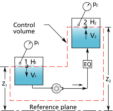
Figure A-1

Figure A-2
Symbols
A: area: m2 (meter square)
D: pipe diameter: mm (millimeter)
f: pipe friction factor
g: acceleration due to gravity: 9.8 m/s2: (metert/second squared)
H: head: m (meter)
DHP: Total Head: m
DHDS: discharge static head: m
DHEQ: equipment head difference: m
DHF: friction head difference: m
DHSS: suction static head: m
DHTS: total static head: m
DHv: velocity head difference: m
L: length of pipe: m
p: pressure: kPa (kiloPascal)
P.F.: powr factor
P: power: kW (Watt)
Re: Reynolds number
SG: specific gravity; ratio of the fluid density to the density of water at standard conditions
q: volumetric flow rate: m3/s
v: velocity: m/s
W: work: kJ
z: vertical position: m
Greek terms
D: delta: the difference between two terms
e: epsilon: pipe roughness: m
n: nu: kinematic viscosity cSt (centiStoke)
h: efficiency
m: mu: dynamic viscosity
r: rho: density: kg/m3
g: gamma: specific weight: N/m3